Lab 2
Register period is dimensionless. It defines the period of the timer as a number of clock ticks of the clock driving the timer component. Therefore, we can link the value of register period
The default clock of a timer is the BUS_CLK of 24MHz, which makes for a
maximum period of 2.731ms, if you want to increase this you can either :
- Create a counter that increments at every overflow of the timer;
- Create a new clock source by going to the
BUS_CLK, ticking New in Clock type, there you will be able to select any frequency to the clock, the maximum period will change accordingly.
That is basically the point of the question :

Therefore, overflow will be equal to :
-
0000 0000if the timer period has not yet elapsed, -
1000 0000if the timer period has elapsed.
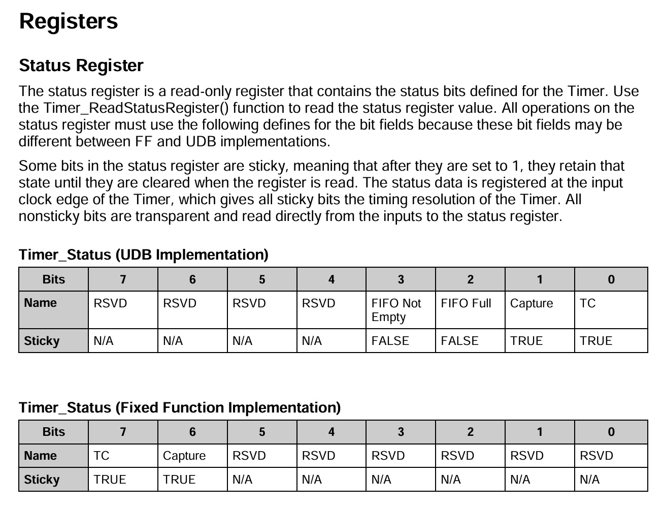
Everything is explained in the datasheet of the timer component in the sections Application Programming Interface and Registers
Please have a look to this (from the datasheet) :
The CY_ISR routine contains a bunch of instructions that should be executed when your interruption is triggered. To make it work properly, you should associate an interrupt (ISR) component (named "isr" for e.g.) to an component-related event in the Top_Design (e.g., overflow of a timer, state of a digital input pin, ect.).
On top of your code (before main thus), you should have something like :
CY_ISR (myISR){
    ...
  // Some instructions here
}
and in the initialization part something like :
int main(void){
    isr_StartEx(myISR);
    ...
    \\ Rest of the code
}
myISR is a Cyaddress poiting towards the routine that should be executed when configured isr is triggered.
Here are some source of errors :
- Forget to link the Interrupt to the Timer in the TopDesign,
- Forget to check On TC in the Timer (TopDesign),
- Forget to enable the Interrupt in the initialization (see
startEx()), - Forget to call
Timer_ReadStatusRegister()at the end of the ISR routine. Needed to reset the timer (the sticky TC bit).
If the sound is bad, you might have sent the wrong signal to the DAC. We are using an 8-bit DAC. Therefore, you cannot send the
- The array signal[N] contains float numbers while DAC expect unsigned integers (uint8). Floats would thus be casted to integers.
- A $\sin$signal is bounded in [-1,1] while the DAC expect a range of integers between 0 and 255. If we do not make proper conversion, we will only end with an array of 0's.

We thus need to make a linear transformation DAC_SetValue(y[n]).
The DAC will then convert the signal into an analog signal and send it to the right output pin.
You should give it this information in the TopDesign. The DAC component should be connected to an analog pin. This pin should be assigned in .cydwr file to the port corresponding to the audio output of your external board (using Extension_PSOC schemes).