This document describes a number of tests that can be performed to verify that the design works as it should.
Within each test procedure, the tests are denoted as bullet-points, followed by some text describing what to do. Results are denoted as "-> something", where something is the expected result.
A description of the hardware is shown below:
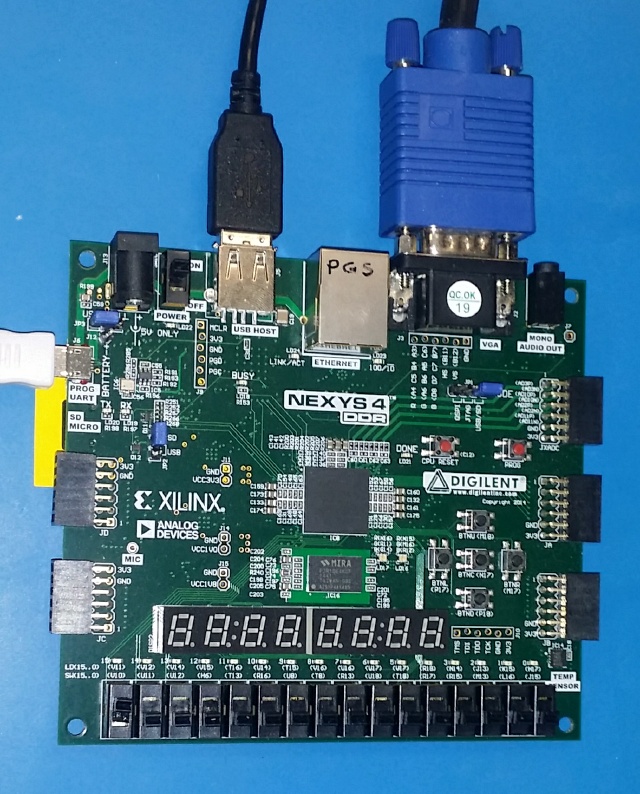 The above image shows:
- Nexys4DDR development board,
- VGA port connected to a vga monitor capable of 800x600 @ 50Hz and 60Hz
- USB port connected to a simple USB keyboard,
- PROG/UART port connected to host-PC, for two reasons:
- to provide power to the Nexys board, and
- to allow serial comms between Nexys and host-PC. The host-PC should have the m65dbg running or a suitable serial-port program. I use picocom.
- SDMICRO port has a SDcard inserted, SDcard should contain the following files at a minimum:
bit03141732_dev..._1541f08~.bit (or similar)BOOTLOGO.M65 (optional)CHARROM.M65MEGA65.D81MEGA65.ROM- FPGA-Switches (SW-x) all in their OFF position, which is DOWN, if using a Nexys4 or Nexys4DDR development board.
All tests, unless otherwise noted, begin with the hardware as described above in the "Introduction" section above.
For the individual tests, please see below.
- Power and BOOT-up - applies power and describes what should happen when the buttons/switches are manipulated.
- c65 mode - navigates around the c65 environment exploring its features.
The End.