Last Updated: 10 November 2019
A robot to draw on a flat surface, with local positioning done through a moving phone camera
- Add a movement system:
- 'Look at me' - the robot turns on its axis to face the camera
- 'Follow me' - the robot continuously moves towards the camera
- 'Trace a shape' - Find a way to upload a vector line file which the robot is able to follow and trace out
- Add a second view to the app, which shows the world from a top-down perspective. This makes it easier to draw, with your finger, the path you want the robot to take. Maybe the original 'camera' view is shown as a little floating window in the corner, like google maps?
- Add a sleep timer, that will HALT the robot after a certain amount of inactivity
- Add instructions for how to connect to the robot
- Add in a dedicated isolation switch that will disconnect the EN1 and EN2 pins on the H-bridge when the ESP is starting up. (Right now this is just done via a wire that is manually moved)
- This project will control a simple 2 wheel drive robot.
- On board the robot, there is:
- an Arduino nano for basic motor control logic,
- 2 simple DC motors for movement
- an ESP8266-01 WiFi chip to allow the robot to communicate with an android app
- Aruco fiducial markers used for easy computer vision.
- The robot has no means of determining it's location onboard, and relies entirely on the android app.
- The ESP8266-01 starts an access point and basic HTTP server when it's powered up to which the android app connects.


- An Android app uses the phone's rear camera to calculate the relative position and rotation of Aruco fiducial markers placed on the robot.
- The app can connect the phone to the robot's access point, and then communicate with the robot via a basic HTTP server setup by the robot.
- The app user can send control commands to the robot, as well as more sophisticated commands that require the information gained by the external camera viewpoint.
- With the addition of a reference Aruco marker placed on the ground, the robot could:
- move towards the other Aruco marker on the floor
- continuously move away from the camera / maintain a certain distance from the camera
- trace a consistent square on the ground while the camera viewpoint changes
- if multiple phones were used, the robot could expand its area of reliable movement to beyond that of just one camera's viewpoint by selecting the closest or most accurate viewpoint


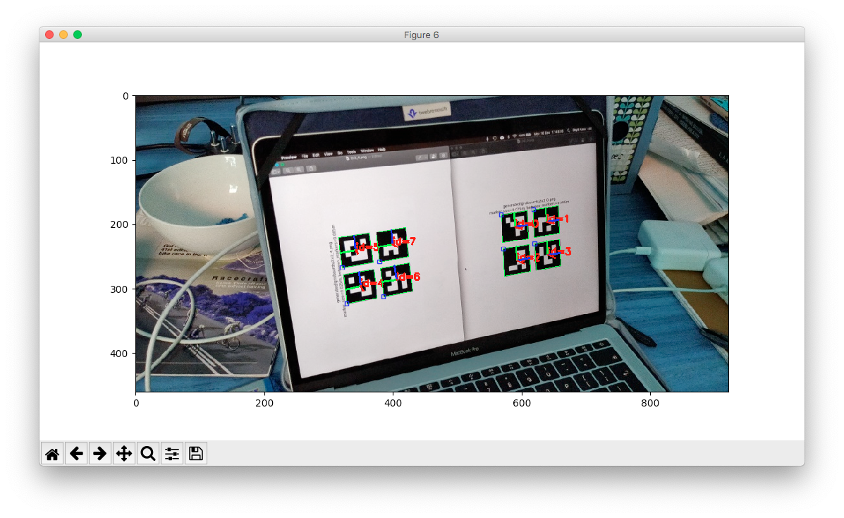
A prototype of the marker detection, pose estimation and projection onto a 2D plane has been developed. The picture below show an image taken with a phone camera where the aruco markers have been detected. The second picture shows a projection of the marker positions and a "normal" for each marker (point showing the orientation of the marker).

Prototype protocols and implementations for wireless remote debugging and receiving location updates on the ESP have been developed.
Mondrian
├── Arduino\ and\ ESP
│   ├── esp
│   │   └── esp.ino
│   ├── james.fzz
│   ├── james.ino
│   │   ├── james
│   │   │   └── james.ino
│   │   └── james.ino.ino
│   ├── james_bb.png
│   ├── nano
│   │   └── nano.ino
│   └── uno
│       └── uno.ino
├── Phone\ Camera
│   ├── Aruco\ Markers.pdf
│   └── OpenCVDeus
│       ├── `// In here is the Android Studio Project`
└── README.md
Unfortunately, the ESP8266-01 can be very finicky, but below is the best way I've found to flash it and upload code.
- Write code for the ESP8266
- Change board to 'Generic ESP8266 Module'
- Compile the code
- Connect the UNO to the computer
- Connect the UNO to the ESP8266:
- UNO Tx --> ESP Tx
- UNO Rx --> ESP Rx
- Click 'Upload' on the Arduino IDE
- Then do this sequence to the following pins
- ESP RESET --> LOW
- ESP GPIO0 --> LOW
- ESP RESET --> XXX
- ESP GPIO0 --> XXX
- You might have to try this compile-button sequence a few times before you see something like this:
Chip is ESP8266EX
Features: WiFi
...
-
After this, push and release the RESET button, and all should be good
-
Possible Errors:
- TODO: Add errors
-
For the NANO, upload nano.ino, but make sure 'ATMega 382P (Old Bootloader)' is selected