Home
INAV GCS uses a layered architecture separating communication, telemetry processing, mission logic, and user interface rendering.
The architecture is designed to support multiple transport layers while keeping the telemetry engine independent from the UI.
Flight Controller
      │
      │ MSP (MultiWii Serial Protocol)
      │
Transport Layer
      │
      ├─ WebSerial (Desktop)
      ├─ Android USB Bridge
      └─ WebSocket Bridge (ESP32)
      │
MSP Parser
      │
Telemetry State Engine
      │
Application Logic
      │
UI Layer (Map + Mission Planner + Telemetry)
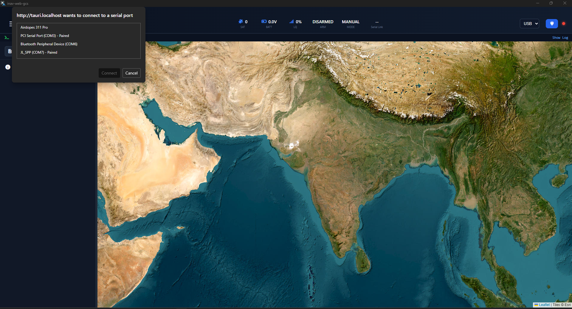
The transport layer is responsible for establishing communication between the Ground Control Station and the flight controller.
Supported transports:
Used on desktop browsers and Tauri desktop builds.
LoRa Ground Module → USB Serial → WebSerial API → INAV GCS
Android builds use a native USB serial bridge through Capacitor.
LoRa Ground Module → USB OTG → Android USB Bridge → INAV GCS
For platforms that do not support WebSerial (such as iOS browsers), an ESP32 is used as a serial-to-WebSocket bridge.
LoRa Ground Module → ESP32 UART → WebSocket → INAV GCS
Communication with the flight controller is performed using the MultiWii Serial Protocol (MSP).
The GCS periodically requests telemetry packets using a polling loop.
Cycle 1 → MSP_RAW_GPS
Cycle 2 → MSP_STATUS
Cycle 3 → MSP_ANALOG
Cycle 4 → MSP_ALTITUDE
Cycle 5 → MSP_ATTITUDE
Cycle 6 → MSP_LINK_STATS
The polling loop runs continuously during an active connection to maintain real-time telemetry updates.
The telemetry state engine stores and updates runtime flight data.
Key telemetry values tracked:
Latitude
Longitude
Altitude
Ground Speed
Satellite Count
HDOP
Flight Mode
Armed State
Navigation Mode
Heading
Battery Voltage
Power Status
Link Latency
Signal Quality
All telemetry values are stored in a central runtime state which is used to update the user interface.
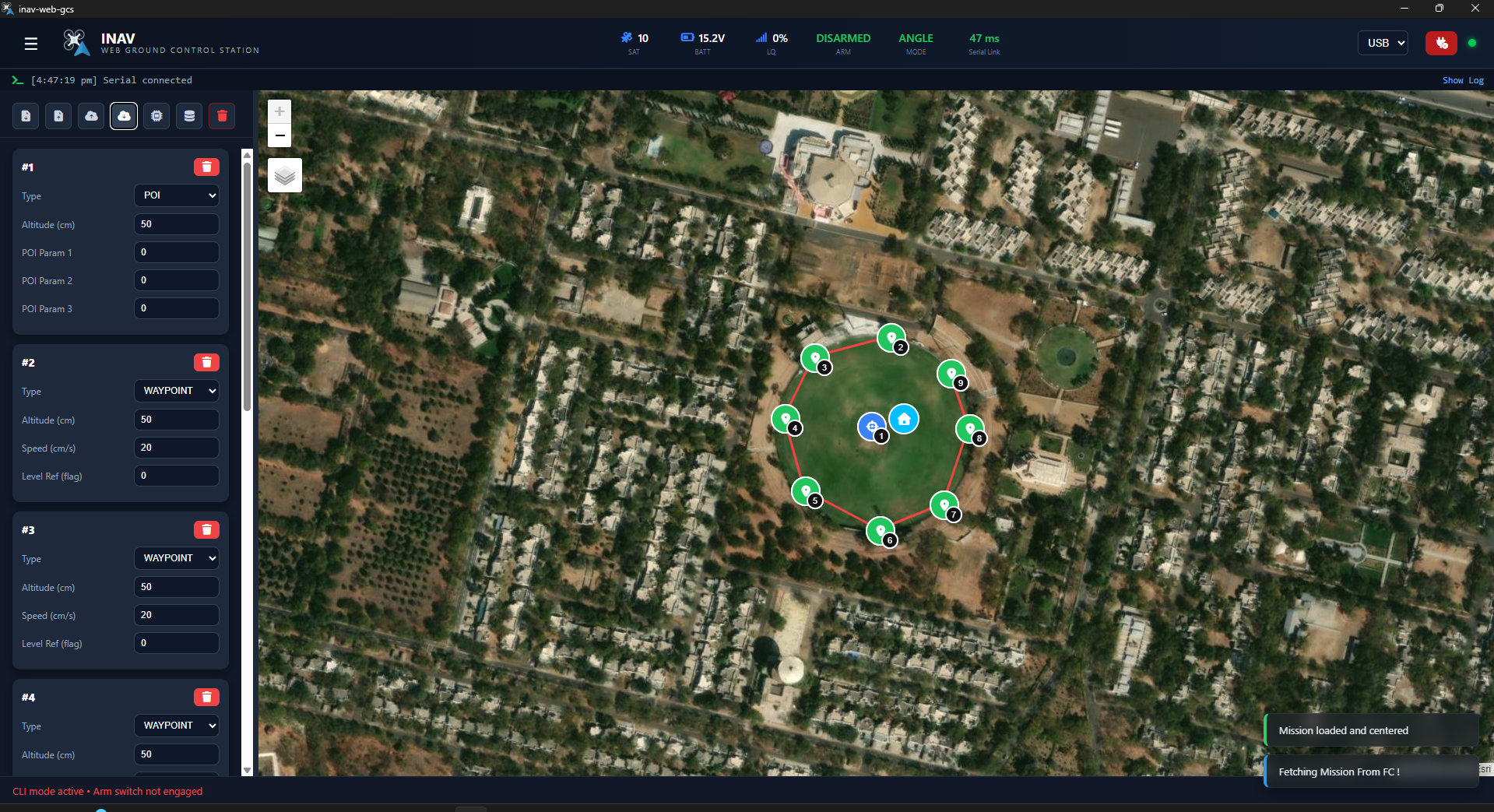
The home location is captured when the drone transitions from disarmed → armed state.
When the arming event is detected:
HomeLat = Current GPS Latitude
HomeLon = Current GPS Longitude
A home marker is placed on the map and used for:
- distance to home calculation
- navigation reference
- mission visualization
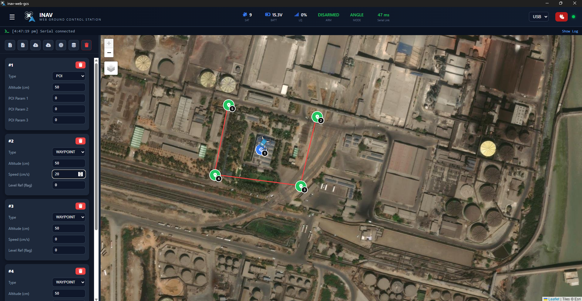
The mission planner allows users to create and edit flight paths directly on the map.
Waypoints are created by clicking on the map.
Each waypoint contains:
Latitude
Longitude
Altitude
Speed
Command Type
WAYPOINT
POI
PH_TIME
LAND
- Drag waypoint markers
- Edit altitude and speed
- Modify command parameters
- Real-time route visualization
Mission routes are rendered using Leaflet polylines.
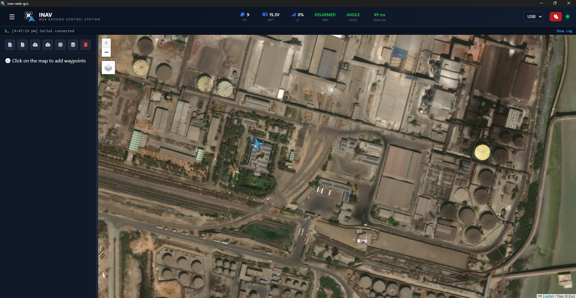
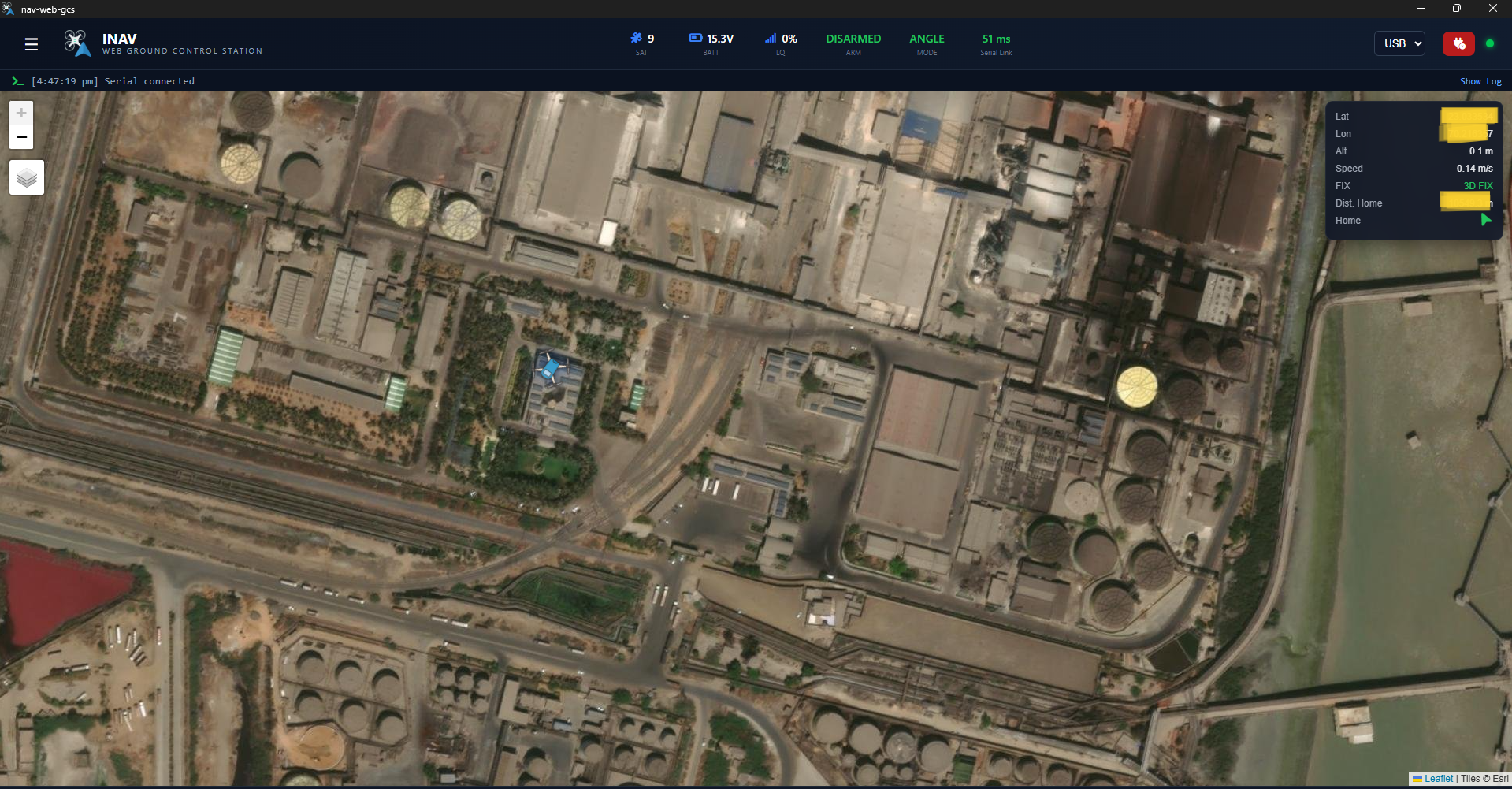
The map interface uses Leaflet.js for rendering.
Features include:
- satellite imagery tiles
- waypoint markers
- drone position marker
- heading rotation
- live flight trail
- mission polylines
Drone movement is smoothed to reduce visual jitter caused by GPS update noise.
Telemetry values are displayed in the top status bar.
Displayed data includes:
Satellite count
Battery voltage
Signal quality
Armed state
Flight mode
Serial link latency
The drone position is continuously updated on the map using the latest GPS coordinates.
The system supports long-range telemetry using LoRa-900A modules configured as transparent serial bridges.
These modules extend UART communication wirelessly.
INAV Flight Controller
        ↓
UART
        ↓
LoRa-900A (Air Unit)
LoRa-900A (Ground Unit)
        ↓
USB Serial / UART
        ↓
Ground Control Station
LoRa modules forward MSP packets without modification.
For devices that do not support serial APIs, an ESP32 can act as a bridge between UART telemetry and WebSocket connections.
LoRa Ground Module
       ↓
ESP32 UART
       ↓
WebSocket Server
       ↓
Browser
The browser GCS connects to the ESP32 WebSocket endpoint and communicates with the flight controller.
Main project directories:
src/core
MSP parsing and telemetry logic

src/transports
Serial and WebSocket communication

src/map
Map rendering and waypoint handling

src/mission
Mission planner logic

src/ui
User interface components
The build system uses Vite for fast TypeScript compilation.
The project can be built for multiple platforms.
Tauri
Produces a standalone executable.
Capacitor
Produces an Android APK.
Vite
Produces static web assets for browser use.
Current limitations include:
- Mission upload support is limited
- Offline map tiles are not supported
- Multiple vehicle support is not implemented
- Telemetry logging is not yet available
Planned improvements include:
Mission upload support
Telemetry recording
Offline map support
Multi vehicle tracking
Mission simulation
Verify the telemetry module appears as a serial device in the operating system.
Ensure USB OTG is supported and permission is granted.
Check UART wiring and LoRa module configuration.
Ensure internet connectivity for map tiles.
⚡ Flight Guide — Ground Control Station for INAV
Developed by BeyMaxx from 
Built for the INAV Community