![]()

Do you want to do some basic hardware hacking, but don't want to deal with installing tools? This project makes it (somewhat) easy to get into hardware hacking, requiring only a R-Pi Pico and some wires (and probably logic clips). You can even use your phone instead of a computer! Perfect for hardware hacking on the go.
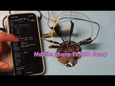
This was a copy (warning: all your base soundtrack) of a BSky video - will upload a better tutorial video when I get some more time:
- Webpage served over USB is the UI, nothing to install on host computers if USB-Ethernet support available (works in Win 11, Linux, Mac probably, Android)
- Python interface (which requires only network interface), solving most annoying USB-driver problems
- UART terminal features:
- ASCII, hex mode, and terminal (vt100) support.
- Can tx hex blocks or specific text blocks.
- Can send characters you type only after enter or or as you type.
- Hot pink & rainbow colour options.
- Download logs
- SPI Flash general features:
- Little ASCII-art of SOIC8 pinout
- Pin activity monitor you can use to see if system is accessing SPI
- Basic sniffer (doesn't keep up with long streams)
- ID-poll loop that looks for SPI access between reading, used to see if you have full control of SPI
- Minimal SFDP read/decoding, and status register read/decoding
- SPI Flash dumping features:
- Supports 3 & 4-byte addressing, hopefully detects correctly which to use
- Option to double-read each block to hopefully detect errors, aborts or retries if this happens with status
- Can display on screen or dump to binary file. Preview data as it's dumping. Partial dumps can be saved if you abort
- Fast enough to not be infuriating for smaller flash sizes (see table below)
- SPI RAW features:
- Send arbitrary SPI commands to a device, including extra padding FF's
- Lets you set 10 quick-access fields to transmit different commands (can change the number in html file)
- eMMC Features:
- Reads ID, sizes
- Scan for empty/non-empty areas to try and avoid wasting time dumping large partitions
- Infuriatingly slow dumping of user partition that you don't want to use for the full 4Gb flash
- Generate .gz (browser dependent)
- Extra-questionable code quality
- Re-enable R-Pi bootloader for easy development without touching a button
- Front-end and much of the firmware code written by AI, I have no idea what it does or how it works (as god intended)
- Change between Dark Mode, Pink Mode, and MS-Dos 6.22 Mode Themes
- Dec/Hex converter on every page
- Randomly disconnects or times out sometimes (surprise feature)
Note vt100 terminal mode requires internet to get the vt100 processing code, this can be moved onto the R-Pi as well but by default I did not for space reasons (there is a stub to copy it to).
Some test on my computer for SPI:
| Flash size | SCK | Double-read on? | Time (MM:SS) |
|---|---|---|---|
| 32 MBit | 1 MHz | No | 0:47 |
| 32 MBit | 1 MHz | Yes | 1:05 |
| 32 MBit | 5 MHz | No | 2:13 |
| 32 MBit | 5 MHz | Yes | 1:06 |
| 512 MBit | 5 MHz | No | 8:50 |
| 512 MBit | 5 MHz | Yes | 17:50 |
| 512 MBit | 1 MHz | No | 12:32 |
| 512 MBit | 1 MHz | Yes | 35:34 |
USB Ethernet is a beautiful idea with an unfortunute history of quasi-standards and different implementations (I even wrote such firmware a long time ago so I have the scars). Luckily this better nowadays, but there are still TWO different imeplementations you can try:
maplelink-X.X-ncm.uf2maplelink-X.X-rndis-ecm.uf2
Try the ncm one first - this is a more recent USB ethernet standard.
The rndis-ecm tries two other standards: RNDIS is a Microsoft 'standard' (but some other devices work with it?), and ECM is an older standard. I may need to release a third version without RNDIS for certain things, but will wait to see if that is needed.
Nightly builds are published with stable links:
Drag & drop the .uf2 file onto a R-Pi pico in bootloader mode.
I didn't need a driver for ncm in Windows 11, but I can provide signed drivers if required, open an issue if this is the problem.
The current firmware is hard-coded to serve a webpage on http://192.168.7.1. Your computer should get an IP automatically (192.168.7.2). If you can't access the webpage, check in order:
- Check you have a new network interface - it might get a weird name, on Windows it shows up under "Network Interface"
- Check you got an IP assigned from this interface
Local settings like VPN enforcing tunneling may prevent access to the network.
The LED on the R-Pi Pico has 3 states:
- Fast blinking (3-5 blinks per second) = power but no USB action yet
- Fast blinking but in blink / blink / off / off pattern = enumeration failed
- Slow blinking (1-2 blinks per second) = enumeration successful, no webpage connection
- Solid = webpage connection
You should get slow blinking until you access the website.
If you are unsure about slow vs. fast blinking, plug the USB into a power adapter instead of a computer. This will trigger the fast blinking mode.
So far tested on Pixel 8A running Android 16:
- Used NCM firmware.
- Plugged into a basic USC-C hub (just 4x USB-A ports) to go USB-C --> USB-A --> Micro-USB A.
- I had to TURN OFF both Wi-Fi & Mobile Internet for it to use the USB-Ethernet connection. Try at least turning off Wi-Fi. Airplane mode alone didn't work either.
Search "USB Ethernet Adapter" for your specific phone model for any device-specific information. It seemed people reported varying degrees of success with needing to turn off other data (wifi etc).
According to https://www.macrumors.com/2023/09/22/iphone-15-usb-c-to-ethernet/ iPhone 15 and later support USB Ethernet adapters.
You may want to use a R-Pi Pico clone with a USB-C port to make this less painful physically (or get a forbidden USB-C to Micro-USB cable).
- Open the Terminal tab.
- Set serial parameters:
Baud,Data,Parity,Stop,Enter.
- Choose send mode:
as you type: sends each character immediately.on Enter only: buffers until Enter.
- Choose decode mode:
plain: raw text.ansi colors: interprets ANSI color escapes.vt100 (xterm.js): full terminal emulation (requires internet by default).
- Optional display controls:
Terminal Theme:default,matrix,rainbow,pink,hot pink.hex view: enables a hex view of incoming dataHex cols: defines the hex widthHex gap ms: After this many ms of no data, will make a new line in the hex view (to help with packets)Backlog KB: limits log sizeDisable Autoscroll: stops terminal from jumping to bottomlocal echo: normal terminal stuff
- Send data:
Send Textfor plain text, will interperate\n,\r,\t,\0,\b,\f,\v,\\,\",\',\xNN(byte),\uNNNNand\u{...}(Unicode)Send Bytesfor hex byte sequences (01 02 FFor0x41,0x42). Both of these save recently sent.
- Logs:
Download Text Logexports terminal text.Download Raw Binaryexports raw RX bytes.
- In Pin Monitor, run
Start Pin Detectto view MOSI/MISO/CS/CLK activity while system is running. - Stop the Pin Monitor
- In ID Poll:
- Click
Monitor activity between polls. - Click
Start ID Poll.
- Click
- Watch:
Between PollsandWindow Activityfields.INTERFERENCEindicates external activity on the bus.
If it is reading a valid ID and says CLEAR between reads, this indicates you might have a good link.
NOTE: The frequency display is not accurate as just polls, but gives some idea of if things are busier or less busy, so have left the numeric display in.
- Setup link as above.
- Perform ID Poll & SFDP read to get flash information.
- This should auto-fill the "Dump Length", and detect if
Addr Bytes(3or4) is needed. - Set
Double-read verifyif you want a more reliable dump - this will attempt each read twice. Set the number ofAutomatic Retriesif you want it to also retry on failed (instead of aborting). - For on-screen preview only (recommended to check data looks reasonable).
- Use Display: set
Display Length, clickStart Display.
- Use Display: set
- For capture:
- In Dump to file, set
Filename PrefixandDump Length(should be auto-filled). - Click
Start Dump. - Click
Stop Dumpif needed (partial data is still kept in UI memory). - Check the full dump is done (shows as complete), otherwise check if there was a read error.
- Click
Download Bin.
- In Dump to file, set
- In SPI tab, use
Read SFDPto parse density/address mode/read command hints. - Use
Read Status Registerto read/decode SR1/SR2/SR3 and common protection bits. Start Sniffercaptures SPI transactions - this samples both MOSI & MISO, so it uses PIO instead of the SPI hardware blocks. This is not a well tested area, it won't keep up with long data stretches and is likely to miss data.
⚠ ⚠ WARNING: HIGH RISK OF PERMANENT AND NON-OBVIOUS PIN DAMAGE TO PICO ⚠ ⚠
PIN2PWN mode will look for a trigger of activity on the SPI lines, then drive them high from the R-Pi Pico. You select one line to serve as the trigger, which can see a specific number of transitions.
If you blow up your pins, you can change them in src/proto_spi.c. For example here are some other good pins:
#define SPI_MISO_PIN 16
#define SPI_CS_PIN 17
#define SPI_SCK_PIN 18
#define SPI_MOSI_PIN 19
I found that some devices would quickly cause the R-Pico pins to be damaged from conflicting. This manifested as unreliable SPI communication after trying PIN2PWN, so it's not obvious but results in frustrating work later.
More ideally you would drive the SPI line with a transistor connected instead - this would result in pulling the pin down, but that will still 100% work.
- Open SPI RAW tab.
- Set SPI speed with
Apply Speed. - Use command rows to send arbitrary SPI byte sequences (with optional extra clocks/padding as configured in UI).
- Read TX/RX in the raw log area.
eMMC mode uses only three pins on the eMMC, which limits data speed greatly:
- D0
- CMD
- CLK
I was able to get around 200 KB/s dumping speed, which means you won't want to dump the full files. The device implements some searching modes to try and find more interesting (non-empty) areas so you can dump specific areas to decide how much effort you want to put into dumping the full flash.
- Open eMMC tab.
- In Safety and Link:
- Set
Tri-state by default,Pull-ups enabled. - Set
Speed,Retry Idle. - Click
Apply I/O SafetyandApply Speed.
- Set
- Use:
Start Pin Detectfor raw pin activity.CMD Test Waveform,CMD1 Sequence Test,SD Init Testfor link-level checks.
- Use
Start ID Pollto repeatedly read ID/OCR/CID/CSD.
- Click
Read Layoutto fetch EXT_CSD layout fields. - Use
Full Dump Hint/sec_countoutput to estimate full user-area size.
- Configure:
Filename PrefixStart LBABlocksChunkDouble-read verifyVerify retriesAuto retries
- Click
Start Dump. - Monitor:
- Progress line (bytes + current LBA)
- Rate/Avg/ETA
- Error counters (
CRC,no-R1,resync,tx-busy)
- Click
Stop Dumpfor partial capture if needed. - Download:
Download Binfor raw binary.Download GZipfor compressed binary (browser-dependent support/performance).
- eMMC filename format:
PREFIXSTARTLBA_ENDLBA.bin(or.bin.gz)
- Configure:
Start LBASample Every n=(sampling stride isn+1blocks)Total SamplesMin Span (blocks)display filter
- Click
Start Scan. - Table outputs grouped ranges:
Type:emptyornon-emptyStart LBA,End LBA,Span,Size
Min Spanonly filters what is shown; it does not change collected data.Clear Resultsclears the table view.
- Configure:
Start LBAMax Search Length (Blocks)
- Click
Start Find. - It scans forward and stops at first non-empty block, or reports not found.
- Status line shows running progress and final result.
- Open DEBUG tab.
- Set debug level (
0..3) withApply Debug Level. - Use
Read Debug Levelto confirm runtime level. Clear Debug Logclears UI debug output.Enter BOOTSELreboots Pico into USB bootloader mode.- About panel includes firmware/build timestamp and project links.
- In
Network, you can setDevice IPand DHCP range (DHCP Start/DHCP End). - Applying network config saves settings in flash and reboots device.
- Stored network config is invalidated automatically when firmware build changes.
See the python folder, but a quick example:
from maplelink import MapleLinkControlClient, MapleLinkSerial

# 1) Serial (pyserial-style API over MapleLink WebSocket)
ser = MapleLinkSerial("192.168.7.1", baudrate=115200, timeout=1)
ser.write(b"help\r\n")
print(ser.readline())
ser.close()

# 2/3) SPI + eMMC over MapleLink WebSocket control channel
with MapleLinkControlClient(host="192.168.7.1") as ml:
    spi_id = ml.spi.read_id()
    print("SPI ID:", spi_id)

    spi_dump = ml.spi.dump(start_addr=0, length_bytes=4096)
    print("SPI dump bytes:", len(spi_dump.data), "state:", spi_dump.state)
Provided you have the USB-Eth working, it works well inside of most environments (including working on WSL on Windows for example)
Some notes for either the human or clanker working on this thing.
Firmware follows normal R-Pi Pico development, with a SDK externally held:
- Clone the pico-sdk or download a release (if cloning be sure to init/update submodules - this project was developed on 2.2.0)
- Clone the repo somewhere for this project or download a zip-file. Then in the root of that folder run:
cmake -B build -G "Ninja" -DPICO_SDK_PATH="/path/to/pico-sdk"
cd build
cmake --build .
This should make a .uf2 you can drag onto the R-Pi Pico in bootloader mode.
If you need some of the SDK tools, you can get pre-build versions from the pico-sdk-tools repository, make sure they match your SDK version.
On Windows, you will likely want to download picotool and pioasm (must be the SAME version as the SDK) and pass the directory with -Dpicotool_DIR="/dir/to/picotool and -Dpioasm_DIR="/dir/to/pioasm for the first cmake. You can also pass paths to the compilers directly, in case you are using older compilers (e.g., like you got from the R-Pi Windows SDK) with a current pico-sdk. Here is both of those shown:
cmake -B build -G "Ninja" -DPICO_SDK_PATH="C:/dev/pico_sdk-src" -DCMAKE_C_COMPILER="C:/devtools/Pico SDK v1.5.1/gcc-arm-none-eabi/bin/arm-none-eabi-gcc.exe" -DCMAKE_CXX_COMPILER="C:/devtools/Pico SDK v1.5.1/gcc-arm-none-eabi/bin/arm-none-eabi-g++.exe" -Dpicotool_DIR="c:/devtools/picotool" -Dpioasm_DIR="c:/devtools/pioasm"
If your build fails when trying to build picotool this is because it did not find a matching version, and is attempting to build it. On Windows you may not have a regular C/C++ compiler so this will fail. The pioasm tool is needed for the PIO blocks (note the tool is pioasm, NOT picoasm). When passing the directories if using pre-built you must pass the path to the folder with the tool, NOT the path to the binary itself.
The eMMC code is needlessly slow, in particular I think some of the bit counts are off. I manually fixed some items but it's also uses some extra clock cycles around to get this working.
- Edit the web page in
src/web/index.html. - During build, CMake runs
tools/embed_html.pyautomatically to generate:build/generated/index_html_data.h
- Firmware serves the generated HTML via
src/http_custom_files.c.
Use the CMake cache option:
BROWSERIO_XTERM_SOURCE=CDN(default): loads xterm from CDN URLs.BROWSERIO_XTERM_SOURCE=LOCAL: expects local/xterm.jsand/xterm.cssassets viaxterm_asset_get.