| My dev notes on using the M5Stack CoreMP135 |
 |
 |
|---|
Thanks to @Johandevlabs, fellow user including notes to install older WifiDongle : https://github.com/johandevlabs/CoreMP135-Debian-notes
Another usefull fellow user : https://remyhax.xyz/posts/m5stack-coremp135/
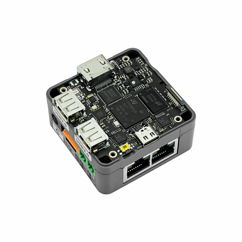
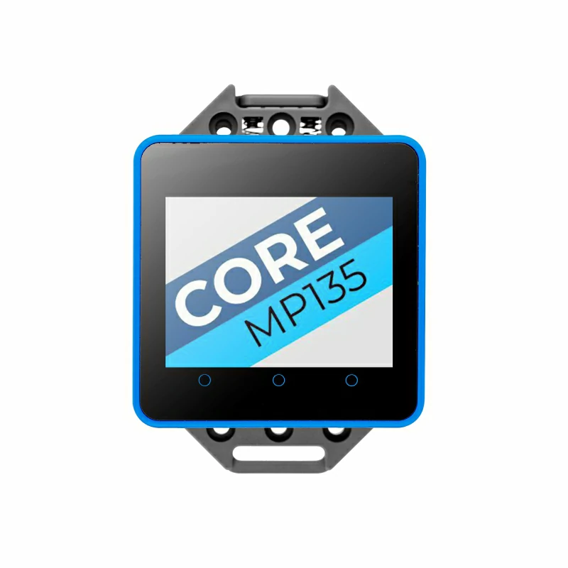
M5stack CoreMP135
Main M5Stack links
Lolin stm32MP157-dk build instructions
M5Stack_Linux_Libs
CoreMP135_buildroot
CoreMP135_buildroot-external-st
Buildroot Tutorial
Schematic mid Layer
Schematic CPU
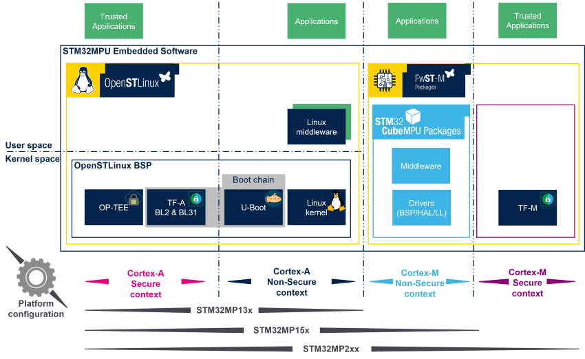
STM32MP - ARM Cortex-A & Linux
Arm cortex-A provides Secure and non-secure execution modes. This presentation explains how peropherals are initialized
OpenSTLinux ARchitecture details
- Once Image is burnt (sdcard.img ) to sdcard using BalenaEtcher 1.18.11 ( 1.19.25 was returning an error on file open )
- pre-compiled images
- connect to device using Putty + USB-c interface -- Windows device manager to find the COMx number
- login: root
- password: (none)
cd /usr/local/m5stack ./resize_mmc reboot
- create new user that will be able to access the device via SSH with sudo rights ( always better not to use root )
adduser usermod -aG sudo
https://stackoverflow.com/questions/53374999/custom-u-boot-environment-variables-using-buildroot
1- On power-up, the CPU checks BOOTn pins ( 1-0-1 ) and starts loading from SD card.
2- SDcard first partition contains linux U-BOOT U-Boot is a bootloader that does minor CPU initialisation and starts loading the linux kernel file based on u-boot config, the kernel file might need to be signed and/or encrypted u-boot initialize the uart terminal pins, the base LCD init with startup-logo
3- Linux kernel start
On device power-up, a CoreMP135 logo gets shown within 1-2 seconds.
This one is transfered to the LCD via spi via the UBOOT bootloader command "show_logo"
Whitin your (workpath)/CoreMP135_buildroot Directory
make uboot-menuconfig --> Boot options > Autoboot options > Delay in seconds before automatically booting = 0 ( way faster ! )
make uboot-rebuild ( will download the uboot-custom package ready to modify and generate a new uboot-nodtc.bin )
make arm-trusted-firmware-rebuild ( will update the fip.bin from the uboot-nodtc.bin previously updated )
make ( will generate a new sdcard.img file )
output/build/uboot-custom/cmd/cmd_show_logo.c
Quick BMP to "C" code convertion: https://notisrac.github.io/FileToCArray/ BUT output file creates 16bits array ... using convert.py to generate proper 8bits array
diff -u "old_file" "new_file" > file.patch
Copy you sdcard.img to a previously programmed and actively running CoreMP135 device
scp output/images/sdcard.img ericadmin@CoreMP135:.
install your target sdcard into the USB2.0 interface of CoreMP135
sudo dd if=sdcard.img of=/dev/sda bs=1M status=progress oflag=dsync && sync or self update dd if=sdcard.img of=/dev/mmblk0 bs=1M && sync
STM32MP1xx platforms from ST uses the STlinkV2.2 mounted to UART4 but the M5Stack CoreMP135 uses those pins differently.
M5Stack changed DTC files to use USART6 ( port-C ) in linux resolving to ttySTM0
BUT
it doesn't work so far with my trials on u-boot.
found in OpTEE-os-custom: ~/CoreMP135/CoreMP135_buildroot/output/build/optee-os-custom/core/arch/arm/plat-stm32mp1/platform_config.h line 177# #define STM32MP1_DEBUG_USART_BASE UART4_BASE > changing to UART6_BASE
found in /home/ericb/CoreMP135/CoreMP135_buildroot/output/build/optee-os-custom/core/arch/arm/plat-stm32mp1/conf.mk line 330# CFG_STM32_EARLY_CONSOLE_UART ?= 6 ( was 4 !!!)
make optee-client-rebuild
make optee-os-rebuild cd outp cdasd
Port C can provide UBOOT bootup information --> TX and RX pins are REVERSED
modern character device (char device) interface /dev/gpiochip0 deprecated (sysfs) interface /sys/class/gpio/gpiochip0
references to help better understand GPIOs within linux: https://github.com/gpiozero https://gpiozero.readthedocs.io/en/stable/index.html https://libgpiod.readthedocs.io/en/latest/index.html https://pypi.org/project/gpiod/ https://github.com/joan2937/pigpio/tree/master
- login as root to avoid privilege issues ( will figure out proper user group later )
- show the different cpu "ports"
gpiochip0 => PORTA gpiochip16 => PORTB gpiochip32 gpiochip48 gpiochip64 gpiochip80 gpiochip96 gpiochip112 gpiochip128
# ls -l /sys/class/gpio will
- to activate PB13 ( port B is 16 + offset 13 = 29 )
# echo 29 > /sys/class/gpio/export
- Now, PB13 is shown if you type the "ls" command
# echo out > /sys/class/gpio/PB13/direction
# echo 1 > /sys/class/gpio/PB13/value
# echo 0 > /sys/class/gpio/PB13/value
https://cdn-shop.adafruit.com/product-files/1138/SK6812+LED+datasheet+.pdf raspi wk2812 resource : https://github.com/jgarff/rpi_ws281x
Core2 BUS pinout : https://github.com/m5stack/M5Core2?tab=readme-ov-file#m5core2-m-bus-schematic-diagram PB13 = pin8 CoreMP135 BUS pinout : https://docs.m5stack.com/en/core/M5CoreMP135#m5-bus G25 = pin8 Core2_battery_sk6812 : https://docs.m5stack.com/en/base/m5go_bottom2#m5-bus RGBled = pin8